With the limited room available to actually build the F1000 thoughts had turned to the build process. While I’m not afraid of welding I have been considering other forms of construction to reduce the amount of jigs we would have to use (and therefore store afterwards). It got me thinking, can we just use the chassis itself as a jig?
Initially I thought this might be achievable by using machined bulkheads with multiple threaded holes to which laser cut sheets could be screwed. A floor and sides could then be created in single sheets hopefully giving enough rigidity to hold everything in place while being welded. Simply supports under the nose on the build table would also help keep things steady.
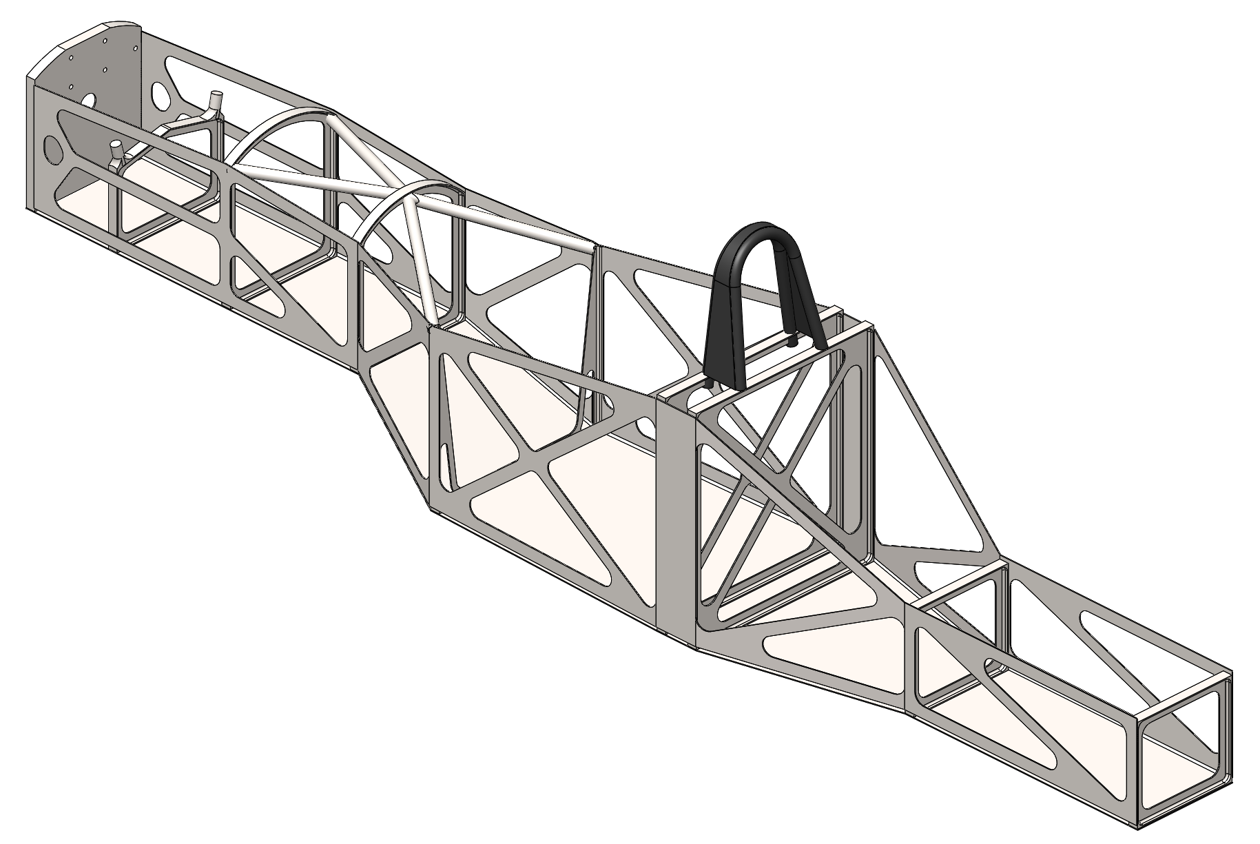
As you can see above it would definitely make things easy to build. There were to be 12 main parts to build the base chassis. 9 bulkheads and 3 sheets laser cut and bent to shape. It soon occurred to me that this may be difficult to get the kind of torsional stiffness required for a racing car. Initially I set about introducing more sheet metal but the more I introduced the more complicated it got, and the more expensive getting all these parts made became. To reduce costs 8 of the 9 bulkheads are now designed to use square tube with square tube also being used between the bulkheads. Using laser notched tube rather than hand notched will mean these supports should slot in neatly and easily. Threaded bosses will need to be welded into the bulkheads to allow the sheet metal to be screwed into place maintaining the chassis jig concept. Another point I forgot the mention was suspension pickup points. The beauty of having the sheet metal laser cut and folded means we can also have holes where suspension clevis’ bolt on in exact positions allowing bosses can be accurately placed.
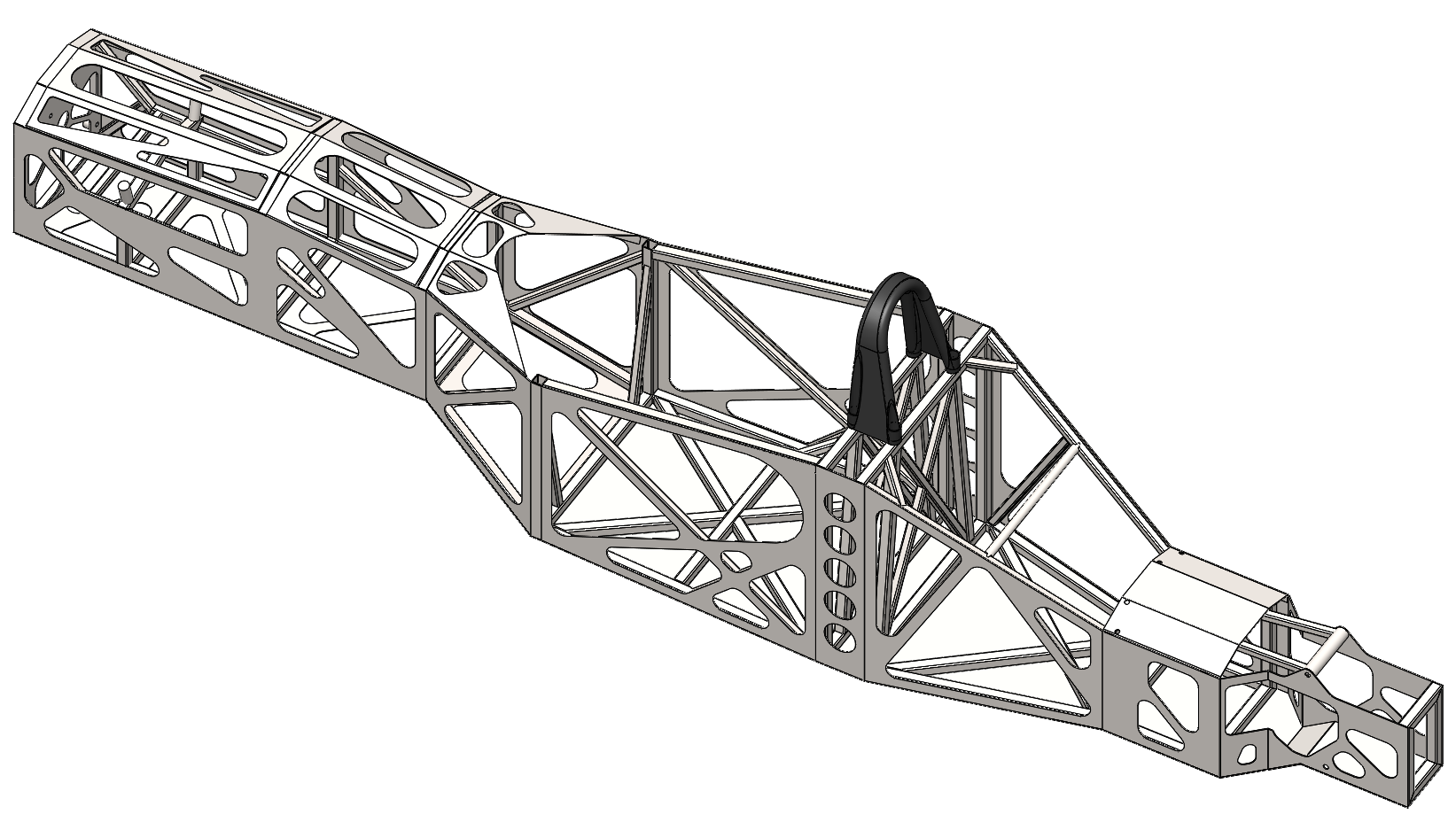
While there is more fabrication that I had initially planed for with this concept once all parts arrive freshly laser cut and bent it should be a quick process to assemble and weld. Next up we’ll be optimising the tube locations and running the stress analysis.