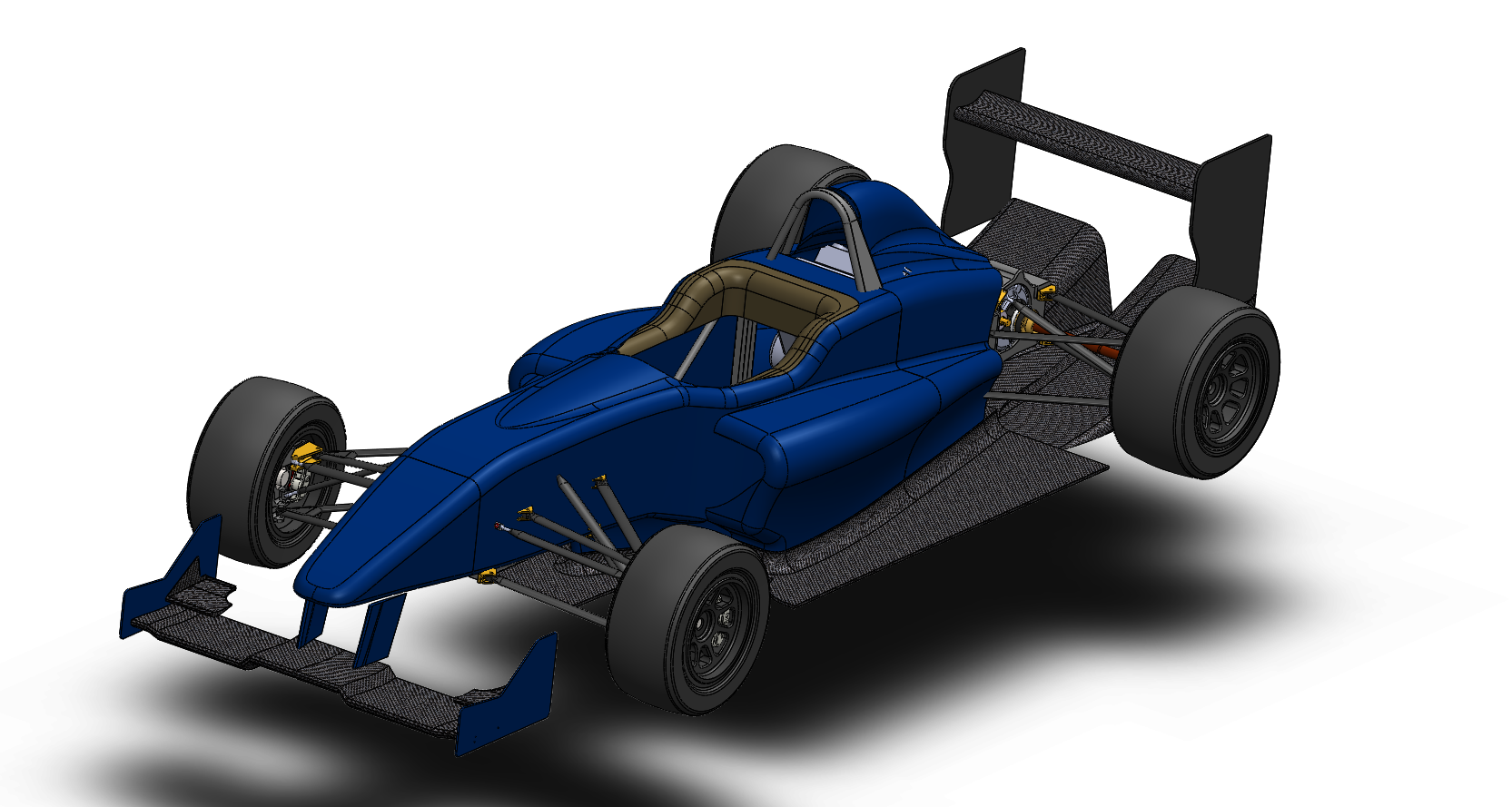
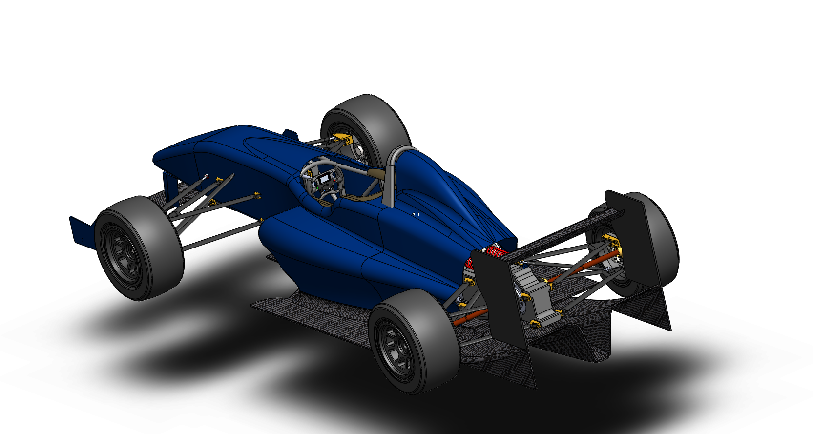
MDS designs and manufactures a wide range of motorsport products and motorsport solutions and it was because of this that this project came about. The Formula 1000 class of open wheeler racing is a class with few limitations and still one of the only classes with open chassis rules and some room for ingenuity and creativity. The MDS F1000 will be created to showcase our design and manufacturing capabilities. Below are our initial mockup designs, and while they look somewhat complete, nearly every part you see will change and be optimised.
Formula 1000
1. DEFINITION
A Formula 1000 is a restricted design open wheel, open cockpit racing car with a mid-mounted engine driving the rear wheels only and intended for use in Speed and Race events.
1.1 The basic design of the vehicles must consist of a space frame chassis made from ferrous metal to which the engine, front suspension, drivetrain and bodywork are attached.
1.2 It must have four wheels of which the rear two are used for propulsion and front two for steering.
1.3 The use of carbon fibre and/or Kevlar composites in any structural components of the chassis or suspension is prohibited.
1.4 The use of titanium alloys is prohibited except for internal engine components.
1.5 The use of magnesium sheeting less than 1.6mm thick is prohibited.
1.6 CAMS reserves the right to require a competitor to fit an approved rev monitor in addition to any rev limiting device that may be fitted in accordance with these regulations. The wiring loom for the rev monitor must be separate and clearly visible.
1.7 Each car shall be fitted with a manufacturer’s ID plate which details the vehicle model and VIN or chassis number.
1.8 Launch control, ABS braking and traction control are prohibited.
2. BODY
2.1 Length: The overall length of the car shall not exceed 4500mm.
2.2 Width: The overall width of the car including the complete wheels shall not exceed 1850mm, when the steered wheels are in the straight-ahead position.
The maximum body width including the under tray shall be 1500mm.
2.3 Height: The height measured vertically from the ground to the highest part of the car with the driver aboard shall not exceed 1100mm, except in regards to rollover protection, which shall not constitute an aerodynamic element.
2.4 Doors: Doors are not permitted.
2.5 Coachwork
2.5.1 Aerofoils are a requirement for this class. (See table 1)
2.5.2 The use of carbon fibre and/or Kevlar for the manufacturing of the bodywork is permitted.
2.5.3 Unless otherwise specified, the coachwork shall be open wheel open body design.
2.5.4 On all cars, the height of any air intakes must comply with Article 2.3.
2.5.5 The underside of each automobile must be a continuous solid flat surface (with a tolerance of ±10mm). This surface must form an integral part of the bodywork and must have no freedom of movement or provision for adjustment in relation to the automobiles chassis. The aim of this tolerance is to allow for manufacturing variations and/or repair of accident damage, which would otherwise render a car ineligible due to its floor not being perfectly flat.
3. EXTERIOR DIMENSIONS
3.1 The entrant shall designate a flat rectangular reference area with minimum dimensions of 300mm by 300mm. This reference area is located on the lower surface of the car between the rear of the front tyre and front of the rear tyre. The center of the reference area must be no more than 75mm from the longitudinal centreline of the vehicle. No point on the lower surface of the car may be below the plane determined by the reference surface on a line perpendicular to that reference plane, except as specifically permitted herein.
Compliance with these requirements shall be accomplished by placing a straight edge on the reference surface designated by the entrant and verifying that the requirements are met.
3.2 A maximum of four (4) rub blocks of maximum dimension 75mm by 125mm are allowed anywhere on the lower surface of the chassis, and may extend below the reference plane.
3.3 A diffuser is permitted behind the front of the rear tyres. The diffuser may be divided internally into multiple sections. The radius of transitions between the diffuser sides and adjacent horizontal structures may be up to 25mm. Strakes within the diffuser are allowed
3.4 The width of the diffuser, as measured between its sides and above any radiuses transitions, shall not exceed 950mm in any lateral section.
3.5 Movable aerodynamic devices, including aerodynamic skirts, are prohibited.
3.6 The width of the entire lower surface of the car between the rear of the front tyres and the front of the rear tyres shall not exceed the maximum width of the bodywork by more than 50mm and shall not exceed 1500mm.
3.7 No part having an aerodynamic effect and no part of the bodywork may under any circumstances be located below the geometric plane of the flat reference surface.
3.8 Any part having an aerodynamic effect and all parts of the bodywork must:
(a) Be rigidly secured to the entirely sprung part of the car (chassis/body unit);
(b) Must be solidly fixed and must remain immobile in relation to this part while the car is in motion.
3.9 If the vehicle is fitted with an external fuel filler, the engine cover and its junction with the bodywork/ cockpit must be designed so as to prevent any leakage of fuel into the interior of the engine compartment during refuelling. Holes may be drilled for fasteners, wiring, fuel, brake and oil lines.
4. WEIGHT
4.1 The minimum Racing Weight at any time including the driver with helmet and wearing all apparel (e.g., as at the end of a race or practice) shall be: 475kg
5. ENGINE
5.1 The engine must be a factory standard motorcycle production engine from the following list:
Years of Manufacture
Kawasaki ZX10R 1000 2003 – 2008
Suzuki GSXR 1000 2003 – 2008
Yamaha YZF R1 2003 – 2008
Honda CBR 1000 RR 2003 – 2008
5.2 The maximum engine rotational speed shall be 13,500 rpm or as specified in article 5.2.
5.3 The engine shall be fitted with a rev limiter so as to permit easy access and interrogation by scrutineers. It shall be set to prevent the engine from producing power above the specified rotational speeds.
5.4 The stock ECU shall be used. The ECU fuel map may be changed.
Devices that modify inputs to the ECU (e.g. “power commander”) may be used.
A control ECU may be introduced by AUSF1000. (The intent is to maintain parity across the engine manufacturers and year model. Development of the ECU will ensure availability and use of donor engines beyond 2008.) The cost of the ECU will be the competitor’s responsibility.
5.5 The maximum rotational speed of the engine may be controlled by AUSF1000 on an individual basis. Intent would be to limit HP as not to have an unfair advantage over earlier year model engines. (Within reason to year of manufacture)
5.6 The material, type and number of engine mountings are free, as is the position and inclination of the engine in its compartment.
5.7 The cooling radiator and the lines connecting it to the engine are free, as are the thermostat and the fan, and their location. The water pump is free.
5.8 The exhaust is free. The exhaust pipe outlets shall be directed either rearwards or sideways.
5.9 The engine lubrication system is free.
5.10 The timing chain tensioner may be replaced with another of free design.
5.11 The fuel pump is free
5.12 Supercharging is prohibited.
6. TRANSMISSION
6.1 Gearbox: The gearbox shall comprise factory production standard gears and ratios only. Undercutting is permitted to damaged gears. Each car shall have a working reversing mechanism. It shall be possible for the driver to select the reversing mechanism while seated normally at the wheel and with the engine running. Automatic gearboxes are prohibited.
6.2 Gear selector forks are free.
6.3 Clutch and flywheel: The clutch basket and flywheel are free.
6.4 Final drive assembly: The final drive assembly and differential are free.
7. WHEELS AND STEERING
7.1 Wheels shall be 13 inch diameter with a maximum rim width of 10.5 inches rear and 9 inches front. Material is unrestricted providing it is metal.
7.2 Cars equipped with four-wheel steering systems are prohibited.
7.3 There shall be a continuous mechanical connection between the steering wheel and the steered wheels.
7.4 The minimum weight for each wheel with a dry tyre fitted is:
Front Wheel – 9kg
Rear Wheel – 12kg
8. BRAKES
8.1 Brakes rotors shall be ferrous metal only.
8.2 All pistons in a given caliper shall be of the same size. Calipers shall be ferrous or aluminium alloy
9. SUSPENSION
9.1 All road wheels/axles shall be suspended from the chassis/body unit by a springing medium (i.e., axles or wheels must not be connected directly to the chassis/body unit). The springing medium shall not consist of bolts located through flexible bushes or flexible mountings. There shall be independent movement of the axles/hub carriers/stub axles giving suspension travel from “bump” to “droop” in excess of the flexibility of the mounting location attachments.
9.2 Active suspension systems are prohibited, as are all systems enabling the flexibility of springs, shock absorbers and the ground clearance height of the car to be controlled while the car is in motion. Cockpit adjustment of anti-roll bars is permitted.
9.3 Electroplating of steel suspension elements is prohibited.
9.4 The minimum unsprung weight is as follows:
Front Suspension – 21kg
Rear Suspension – 26kg
The minimum unsprung weight is measured by disconnecting the pushrod and removing the wheels, and does not include the weight of the pushrod or damper (if applicable).
10. FUEL SYSTEM
10.1 Fuel must be a Commercial Pump Fuel in compliance with Schedule G (see “General Requirements for Cars and Drivers”).
10.2 No fuel pumps, fuel filters or fuel lines may be positioned inside or pass through the cockpit unless protected by a cover that is impervious to the passage of flame and/or fluid.
10.3 Fuel tanks must be properly protected. All fuel tanks situated outside the main structure of the car must be surrounded by a 10mm thick crushable structure. The tank must be isolated by means of bulkheads preventing the fuel from passing into the cockpit or engine compartment or coming into contact with exhaust piping, in the event of spillage, leakage or any other accident occurring to the tank.
11. OIL SYSTEM
11.1 All oil tanks shall be properly protected. All oil tanks situated outside the main structure of the car shall be surrounded by a 10mm thick crushable structure.
11.2 All lubricating oil lines operating at a pressure of 350kPa or above shall have a minimum burst pressure of 4100kPa at the minimum operating temperature of 135°C. When flexible, these lines shall have threaded connectors and an outer braid resistant to abrasion and flame (will not sustain combustion).
11.3 No lines containing lubricating oil may pass through the cockpit unless protected by a cover that is impervious to the passage of flame and/or fluid.
12. ELECTRICAL EQUIPMENT
12.1 Batteries shall be located outside the cockpit, unless they are military grade dry cell type. They shall be securely fixed.
12.2 A starter with an electrical or other power source shall be carried on board the car. It shall be possible for the driver to operate it when seated normally in the car. The starter shall be capable of starting the engine at all times.
12.3 The alternator shall be the standard production unit supplied with the engine and shall be fully operational.
12.4 One high-intensity rain light is required, fitted on the centreline of the car, at the rear of the bodywork. Either an incandescent light with a minimum wattage of 20W or a high intensity LED light with a minimum luminous intensity of 18,000 mCd (millicandela). Alternatively, a pair of such lights, fitted symmetrically around the centreline of the vehicle shall be acceptable. The minimum view angle shall be 40° when viewed directly from behind.
13. COCKPIT
13.1 The cockpit seating position shall be central in relation to the centerline of the vehicle.
13.2 The point at which the steering column passes through the dashboard and the pedals are attached to the chassis must be located centrally to the vehicle centreline.
13.3 Footwells: The minimum width of the driver’s footwell is 250mm and this width shall be maintained over a height of at least 250mm.
13.4 The only components that may be fitted in the cockpit are the following:
– Safety equipment and structures
– Driver cooling systems
– Instruments
– Electronic equipment
– Fire Extinguisher
– Seat and control required to drive the car
These components shall be covered by a rigid protection if they have sharp edges, which may cause injury. Their fastenings shall be able to withstand a 25G deceleration.
13.5 Pedals: The soles of the driver’s feet, when seated in the normal driving position with the feet on the pedals and with the pedals in the inoperative position, shall not be situated less than 18cm behind the front bulkhead of the tubular steel frame forward of the vertical plane passing through the centre-line of the front wheels.
13.6 Cockpit opening: The driver’s seat shall be capable of being entered without the removal or manipulation of any part or panel (except for a removable steering wheel and removable cockpit padding). The cockpit opening of the metallic chassis shall have the following minimum dimensions:
• Length: 600mm
• Width: 450mm
The minimum width shall extend over a minimum length of 300mm. This minimal rectangular opening may exist anywhere forward of the bracing, and required padding will not be considered in these dimensions.
The maximum time for the driver to exit the cockpit shall not exceed seven seconds.
13.7 Brake lines may pass through the cockpit provided there are no connections in the cockpit area.
13.8 The steering wheel shall be fitted with a quick release mechanism.
13.9 Where a head restraint is not part of the seat, then a separate head restraint with a minimum area of 180cm2 shall be fitted. Its surface shall be continuous, without any protruding parts. The head restraint shall not deflect more than 50mm under an 850N rearward force. The head restraint shall be located in a position such that it will be the first point of contact with the driver’s helmet in the event of an impact projecting the driver’s head rearwards when he is in the normal driving position. The distance between the driver’s helmet and the head restraint should be kept to a minimum such that the helmet will move less than 50mm under the abovementioned force.
14. SAFETY STRUCTURES
14.1 Safety Cage/Rollover Protection Structure:
The safety cage structure shall conform to Schedule J – Safety Cage Structures, and be of at least Type 1. The material specification and dimensions shall be in accordance with Schedule J.
Alternatively, the safety cage structure may be certified in accordance with FIA Article 277 – Free Formula Technical Regulations.
A safety cage structure approved by an ASN other than CAMS or superseded regulations is not necessarily eligible for competition in Australia. Prior to importing a vehicle, a competitor is strongly advised to contact the CAMS Technical Department.
14.2 Front Impact-absorbing Structure:
The vehicle must include a front impact-absorbing structure installed in front of the driver’s feet, which complies with at least one of the following types:
1. A front impact-attenuation structure meeting the load requirements of FIA Appendix J, Article 277 (evidence of compliance must be supplied).
2. A structure meeting the requirements of the SCCA-approved front impact-attenuation structure specified for SCCA formula cars is permitted for cars with prior SCCA certification.
Page 10 of 10 Formula 1000 Technical Regulations – Version 1
© Copyright Confederation of Australian Motor Sport Ltd 2013
3. This specifies a structure with a minimum cross-section of 200 sq cm at least 400 mm forward of the clutch and brake pedals (non-depressed).
A structure that extends more than 300mm in front of the front bulkhead of the tubular steel frame, with a cross section of 200 sq cm measured at a position 200mm in front of the bulkhead.
Type 2 and 3 structures above must be constructed of either:
(a) A minimum of eighteen (18) gauge 6061-T4 or equivalent aluminium using honeycomb sandwich construction, with a panel thickness of 13.9mm minimum.
(b) Full composite construction of carbon fibre or Kevlar with a minimum of two 141.75g/m2 (5oz) inner and outer layers of laminate over a honeycomb polyurethane foam core with a minimum thickness of 20mm. The impact-absorbing structure shall be securely attached to the front bulkhead of the tubular steel frame. This structure shall be independent of the main bodywork and must be solidly fixed to the extremities of the bulkhead (i.e., with bolts requiring tools for removal).
(c) Aluminium plate / bonded composite panels can be attached to chassis for the purpose of side intrusion but must not constitute a stress bearing panel. (Stress bearing panels are defined as sheet affixed to the frame by welding, bonding, rivets, bolts, or screws which have centres closer than 150mm)