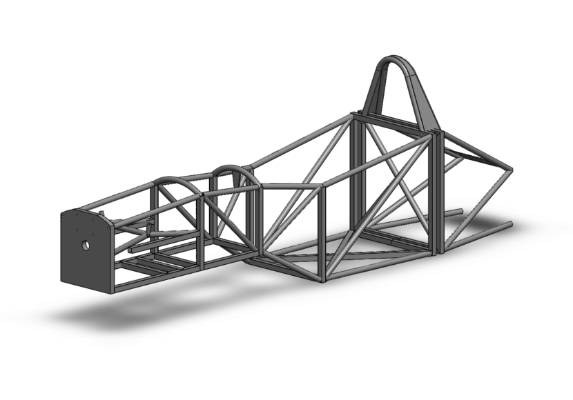
While the suspension kinematics has started it’s also worth investigating how that suspension will feed loads into the chassis. While we have realised that a high nose suspension can work from a kinematics point of view we also need to take into account the chassis design. It soon became apparent that we had not left quite enough room for a drive with large feet to sit inside the chassis, and that from a manufacturing point of view, it was going to be much easier to create inner wishbone pickup point all on the same plane. Doing it this way means we can using the same width chassis bulkheads for the front half of the chassis. This will have knock-on effects with chassis jig manufacture also.
Other areas to consider are where these loads will feed into the chassis. A typical low nose setup would have inboard wishbone pickups at points on the chassis where loads can be spread via axial bracing, however with a high nose there can be more considerations. Our upper wishbones actually feed into the middle of a chassis where extra material cannot be added to brace to the other side – there are feet operating pedals to consider! While this normally wouldn’t be as much of an issue in a carbon chassis where stiffness can be achieved using different layup techniques, the MDS F1000 must make use of sheet and tube steel. More refinement required.
How this all affects the kinematics we don’t quite know yet, but once we can the pickup points sorted we will run through the model again and make any changes where we can on the outboard side (uprights and steer clevis’ will be CNC’d from billet meaning we can put pickup points were we like). Our next steps chassis wise will be to ensure the inboard loads, as well as chassis torsional stiffness meet requirements. More in this in a later post.